 ramblz
 progrz
 thangz
 fotoz
fotozWhy you're probably losing the bottom 1mm of your prints and how to fix it
These two objects are the same .STL and use the same slicer settings, yet one has a properly leveled build plate. It’s likely you’re losing the bottom millimeter of every print you make. In this post I’ll discuss why that can matter and how you can resolve it by properly leveling your build plate.
The most common issue nobody knows about…
Leveling the build plate is one of the first things you’ll do with a new resin printer, and arguably it’s the most important thing to get right when it comes to making prints succeed. So it’s odd that the process has a sort of ‘black magic’ reputation among the resin printing hobbyist community. Everyone seems to have their preferred way to level their build plate, often based on anecdotal evidence from somebody else, or just being the first thing they tried that worked for them.
I’d argue the reason for this is it doesn’t really matter how accurately the build plate is leveled for the majority of users.
See, the common notion is printing straight on the build plate is bad, and prints should be supported and printed at an angle for best results. There’s a lot of reasons why this is generally very good advice (which I won’t go into here), especially when given to novice and intermediate users who just want successful prints.
But printing with rafts and supports means the only thing that matters is whether the print adheres to the build plate. Nothing else is of consequence. This leads to practices that massively over-expose and compress the initial layers to ensure that adhesion, at the cost of accuracy on those layers. E.g. setting base layer expsure to absurdly high values, such as the recommended 10x regular layer exposure (25s for a 2.5s regular exposure with a mono LCD), and leveling with single pieces of standard A4 paper, which means the zero-level of the printer is too low.
This used to be me, too…
Printing flat on the build plate
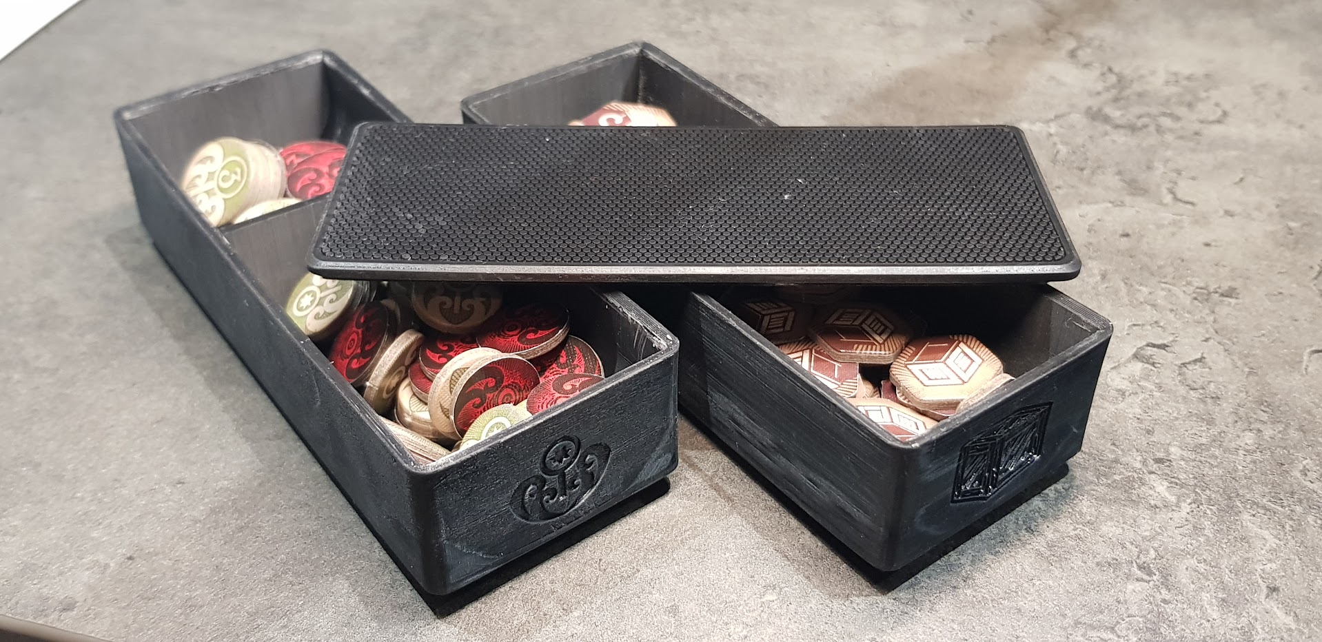
I’ve been printing storage solutions for board game components. E.g. boxes for tokens, dividers for card sets. The alure of printing on the build plate without supports was too strong.
- Less resin used.
- No concerns about supports failing.
- No ugly support artifacts to remove.
- Shorter build time because print isn’t angled.
- Less concern about un-even warping causing low tolerance parts to not fit together (e.g. the box and lid).
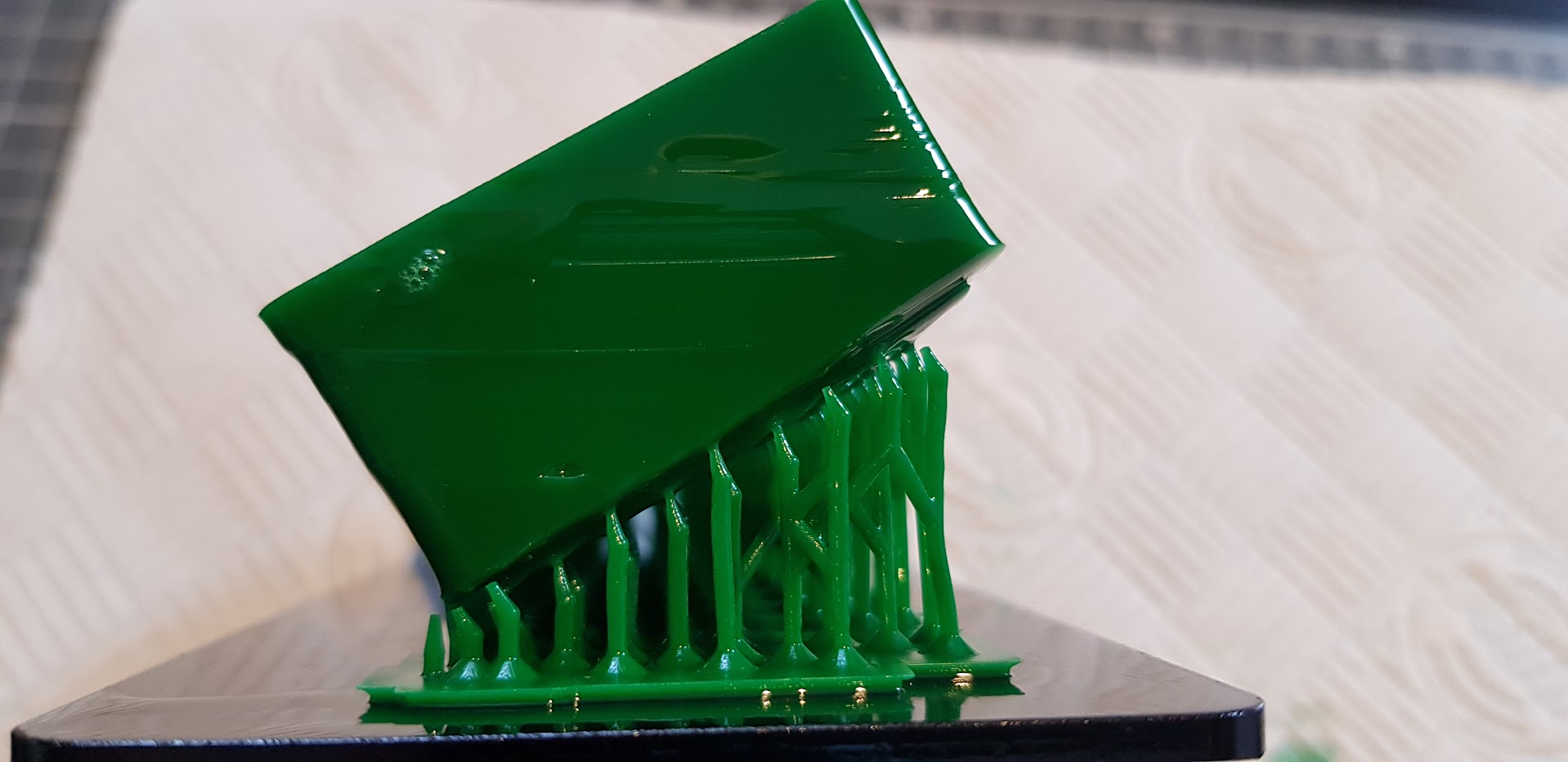 Printing angular objects like this with supports can be a pain…
This was working well for me. There are different problems to solve when printing flat, such as elephants foot, blooming, and shrinkage, but I mostly had these under control thanks to Jan Mrázek’s absolutely excellent articles on these issues.
Jan Mrázek's blog is a fantastic source for those looking for technical solutions to many common resin printing problems. He has articles on blooming, elephant's foot, shrinkage, and (related) warping.
However, there was one thing that kept irritating me. I like to bevel the bottom layers in contact with the build plate, for sliding a spatula underneath for ‘easy’ removal:
I usually make these about 1-2mm tall. But after printing, I always had more trouble than expected removing prints from the plate, often damaging the print or the spatula in the process of detatching. When I looked, it appeared like the bevel hadn’t printed at all.
Bottom layer compression
What was happening, I discovered, was that about 1mm of the bottom of the print was completely gone. Not printed at all, meaning all my prints were ~1mm shorter than they should be.
I did a quick test, making a 5x5x5mm cube and printing it. Lo-and-behold, the cube came out closer to 5x5x4mm, a whole millimeter short:
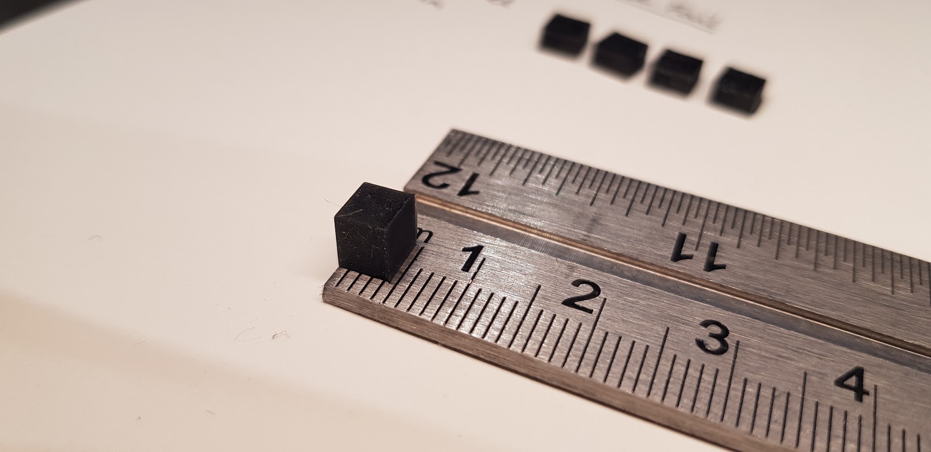 This actually isn’t first cube I printed, this one is only ~0.5mm shorter than it should be.
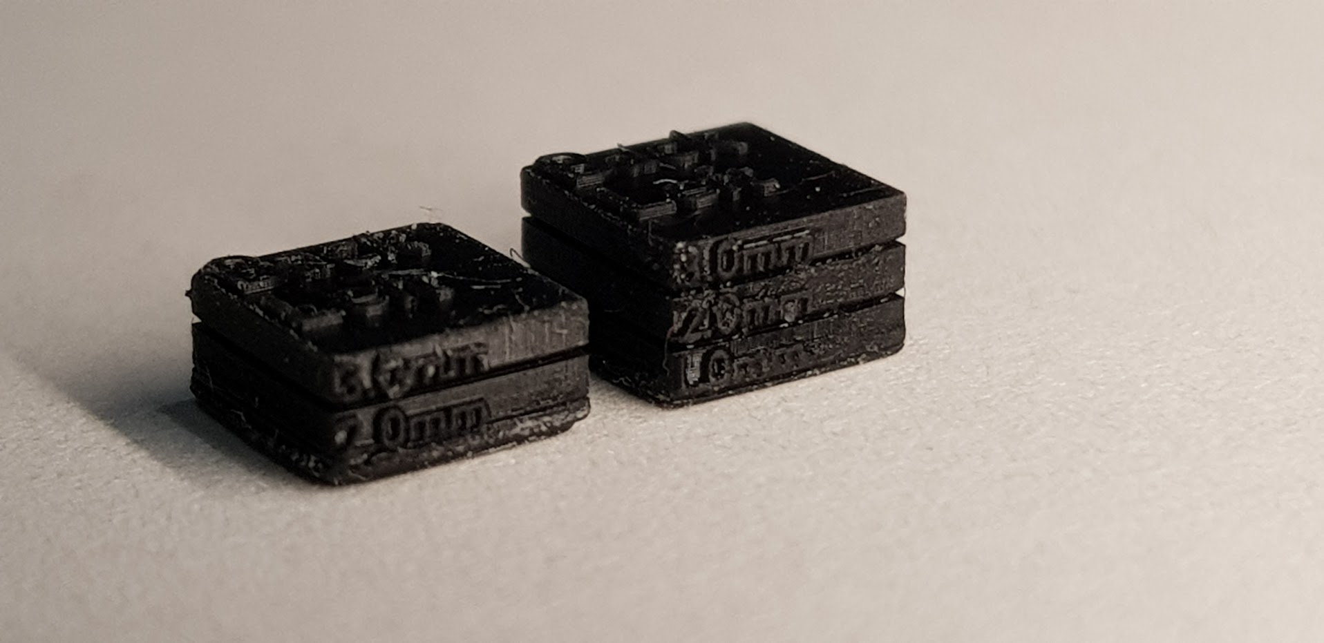
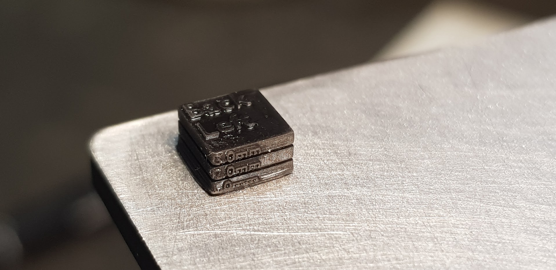
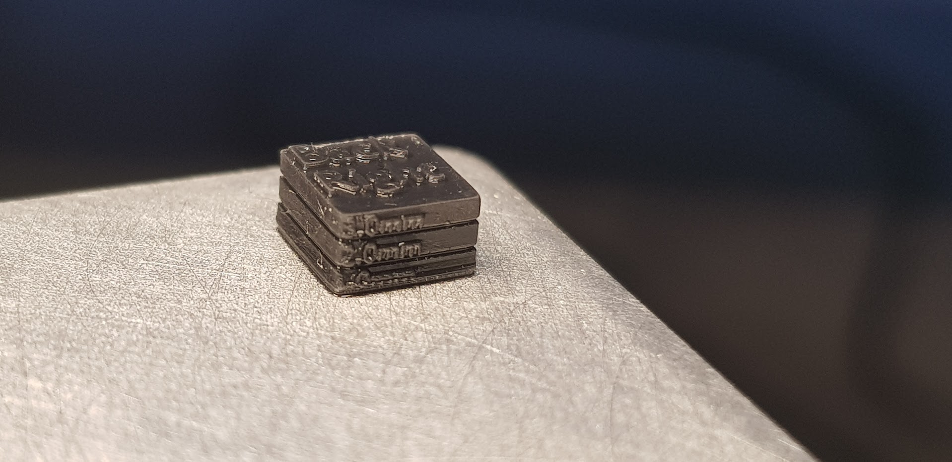
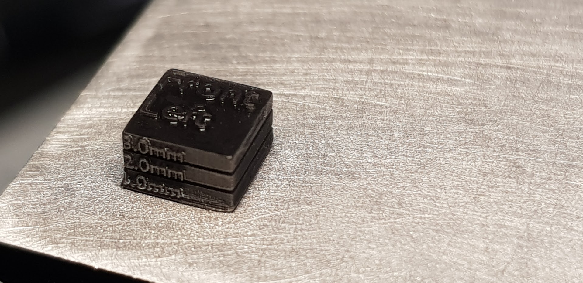
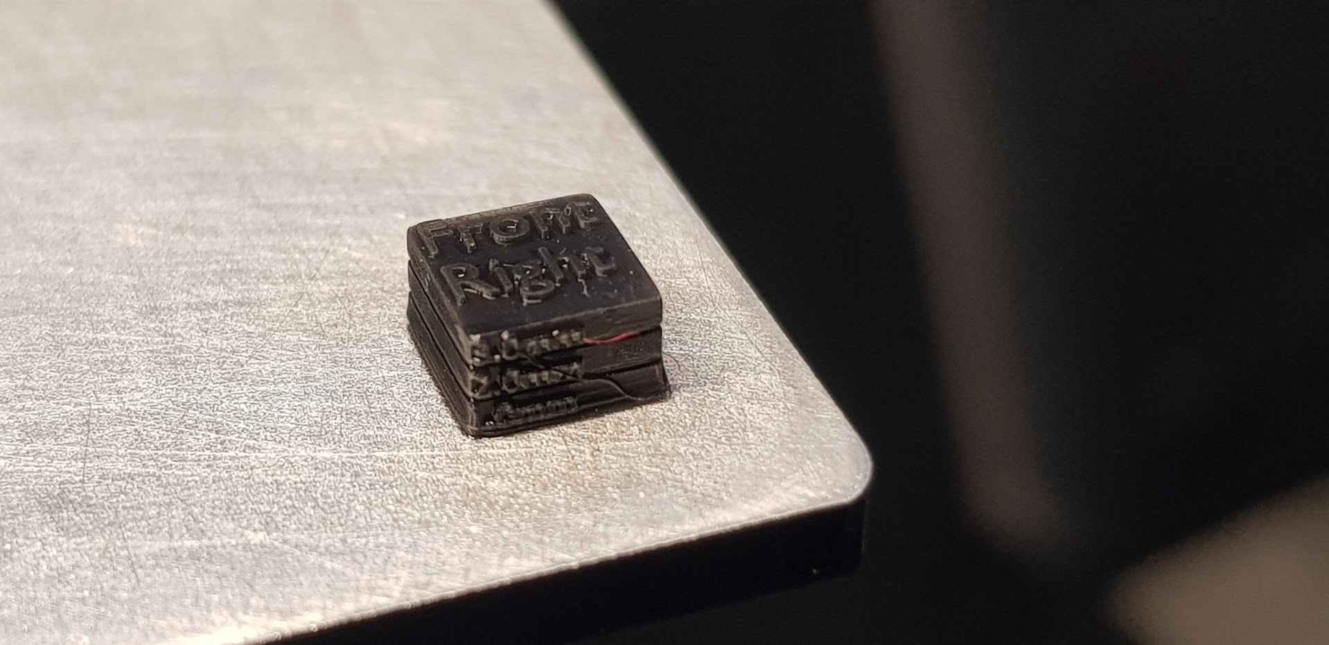
Going a bit further, I hacked up some test cubes in Blender and printed one on each corner of the build plate, and got this:
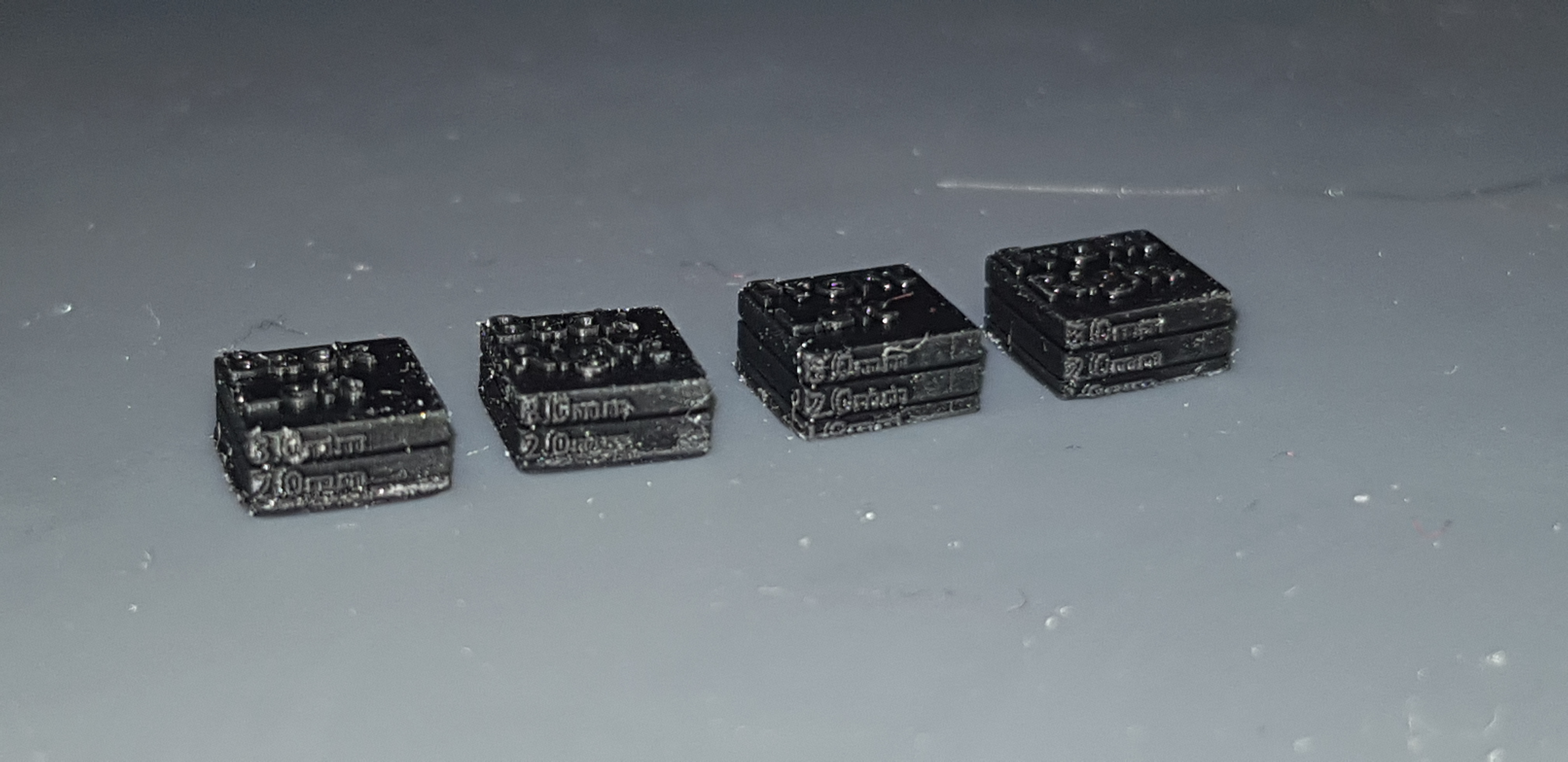 Apologies for the quality here, these objects are really small and when you zoom into improperly cleaned prints it tends to show the imperfections really well.
If you can’t make out the text, on the top of each cube is the corner (top left, bottom right, etc), and on the side are two horizontal markers denoting 1mm and 2mm from the bottom. The whole cuboid should be 3mm tall. The two back cubes are missing almost 1mm, and the two front cubes are missing closer to 0.5mm. This shows that not only is my build plate compressing the bottom layers significantly, it’s also not level, being tilted slightly towards the back.
What’s going on?
When I initially leveled my Saturn 2’s build plate, I used a sheet of A4 paper. I also attempted to ensure the plate was level by testing the force required to remove the paper from all four corners. I then proceeded printing, happy with my successfully level plate and successful prints.
But there was something sinister afoot…
By locking in the zero-level so close to the LCD screen, I was effectively making the print start below the vat, and the first 10-20 layers were inconsequential because the build plate was travelling to the very bottom of the vat every time and being stopped by the LCD itself (or rather, there’s some safety switch to stop the plate before it destroys the LCD).
Not only does this mean the bottom layers are lost, the very bottom layer gets so over-exposed (due to repeated exposures) I was able to reduce the base layer exposure time to only 1-2x the regular layer exposure and still have no adhesion issues!
But this raises the question, why does setting the zero-level of the plate at the level of the vat cause so many layers to be compressed together?
I don’t have a good answer, but my un-educated guess is that there is some built-in compensation in the firmware to start the print lower than the zero-level in an attempt to reduce failed prints from users with poorly leveled build plates. The downside of this would be that if a user has correctly leveled the plate, the compensation over-corrects and we get these compressed layers.
How do we fix this?
The solution is fairly simple, but a little cumbersome. Instead of relying on some perfect combination of leveling paper (single A4? double A4? 180gsm card?), we’re going to do some calibration prints to determine how high off the LCD screen we need to set the zero-level to get a near-to-perfect print with no bottom layer compression.
1. Level
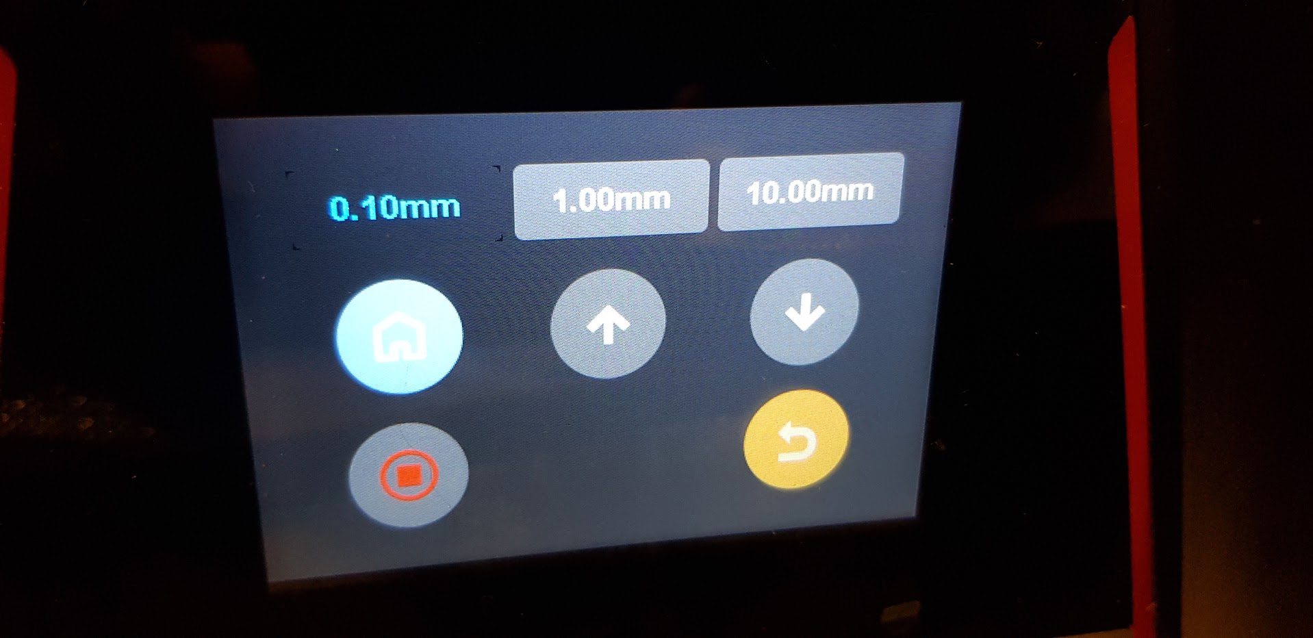
First we ensure our build plate is level, i.e. the height at all four corners is equal. We can do this by leveling with any thickness of paper or card (though it’s important that you stick with this thickness during the whole process), and then making sure each corner requires the same force to pull the paper out. If the force isn’t equal, keep re-tightening the bolts while applying pressure to the corner/side of the plate that requires the least force, until it is equal. Use raise/lower 1mm buttons to insert the paper below a corner, lower the plate, and test for pressure.
2. Measure
Now we have the plate level, we can work on determining the correct height.
Make a test print with cubes in all four corners. Set your base layer exposure time to around 3x the standard layer exposure time. For example, I’m using ELEGOO Standard Black Resin, with a 2.5s layer exposure and 7.5s base layer exposure. Like I said earlier, a high (10x) base layer exposure is a compensation for a poorly leveled build plate, and is unnecessary.
Since we’ve only leveled to the LCD (plus whatever paper used) for now, these cubes will be shorter than they should be. The important thing is to determine how much shorter they are. A good ruler and a good eye should be enough here.
Once we have that…
3. Adjust
Unfortunately, and this is why I said this process was a little cumbersome above, we now need to re-level the plate as we did in the first step (with the paper), but this time apply the height difference we determined in the second step to the build plate before we set the zero-level.
At least on the Saturn 2, it is not possible (AFAIK) to adjust the zero-level by some amount without using the home button first, and using the home button will (AFAIK) destroy the currently set zero-level. So we need to clean the build plate, remove the vat (no need to remove the resin from the vat), and level as we did in the first step.
After re-leveling the plate, but before setting the zero-level, increase the height of the build plate using the buttons by the value you need to. For me, my initial attempt was 0.5mm.
4. Repeat
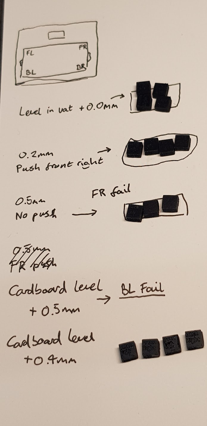
Now, we repeat the second and third steps until we get a print that is the correct height. For me, this took a few attempts, as when I initially raised the plate by 0.5mm before setting the zero-level, I got a few failed prints where some corners didn’t adhere to the build plate, suggesting I’d raised the plate too far. I then re-leveled again and only raised the plate by 0.4mm. It might take a few iterations of this to get the correct zero-level where all corners adhere and there is no bottom layer compression, but if you’re printing flat on the build plate at all, it’s worth it.
Results
With the build plate raised an extra 0.4mm above the paper level, I got an almost perfect print on all four corners:
You can clearly see that each cube is 3mm tall (+/- 0.1mm). The bottom layers are messy, but I wasn’t using any extra wait time to eliminate elephant’s foot and blooming (for lower print time).
If you want to use my cubes yourself, you can download them here.
If you try this and it works for you, I’d love to hear about it!
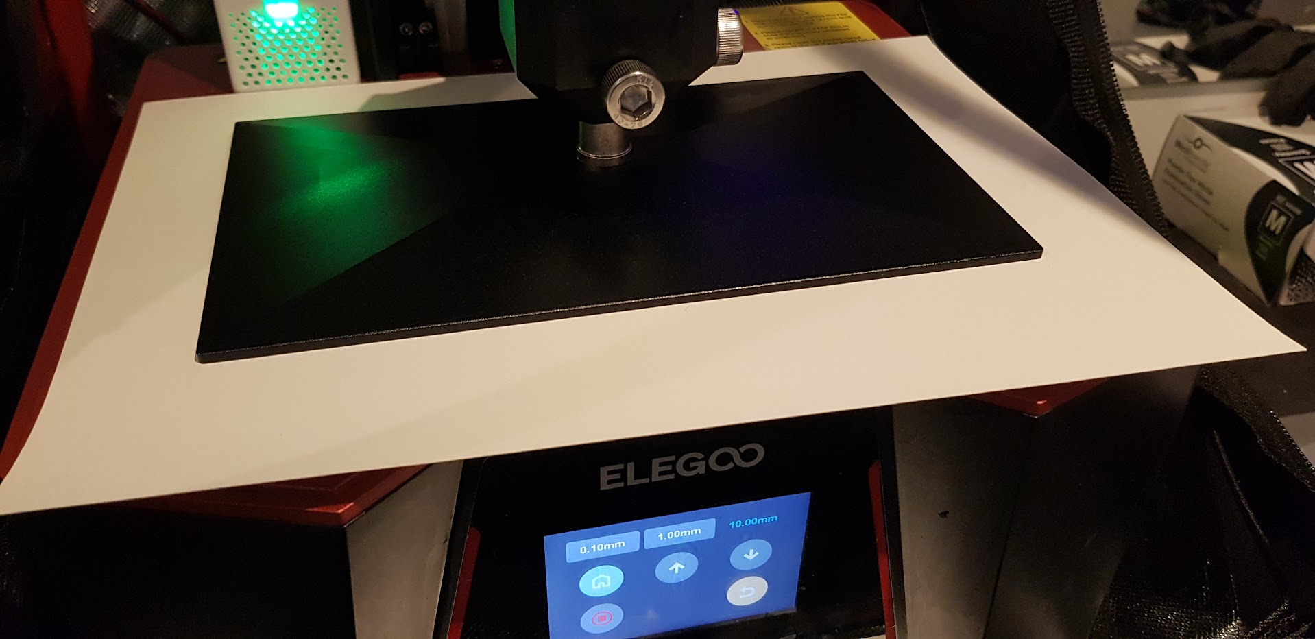
My setup
I conducted this test with the following setup, in-case you want to compare to your own:
- ELEGOO Saturn 2.
- ElEGOO Standard Black Resin.
- 2.5s layer / 7.5s base layer exposure.
- Resin heated between 25C and 30C (usually I would maintain 30C, but it wasn’t critical to this test).
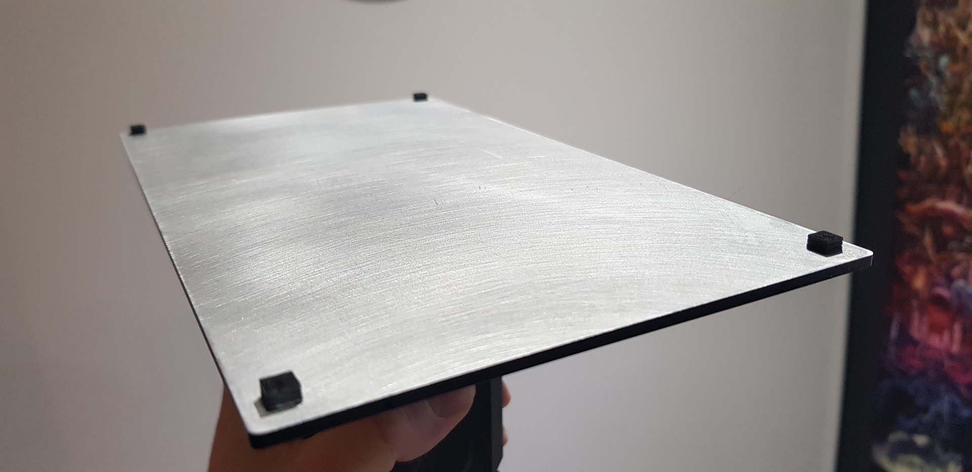
- Build plate lightly sanded for ~1min with 600 grit sandpaper.
Comments
Post comment